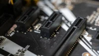
SOLIDWORKS is one of the most widely used CAD programs in industry. It allows users to create interconnected part files, assembly files, and drawing files. Changes to one file are automatically reflected in the other.
SOLIDWORKS is available with a perpetual license or a term license. The latter requires an activation process on first launching the program.
Parametric Design
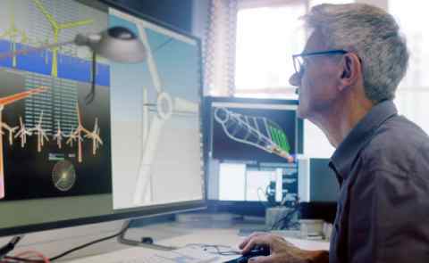
Parametric Design is becoming prominent on a large scale around the world. It has the potential to change architecture in an unprecedented way. It can help create structures that are both visually appealing and efficient.
With parametric design, engineers can easily see how changes to a drawing/model will affect its surrounding components and even the overall project. For example, if a component’s size is increased, it will also affect the hole, joint or fixture it is attached to. This will allow the designer to spot any clashes quickly and efficiently.
This type of design is perfect for architects and engineers who need to solve complex spatial issues. It can produce structures that are both functional and beautiful, like the Tokyo Skytree. This structure uses parametric design to produce a spiraling shape that blends artistic function with maximum efficiency. It has also become a symbol of modern technology, which can change our lives for the better.
Automation
Using SOLIDWORKS, you can automate most tasks to speed up your work processes. This allows you to create parts, assemblies and 2D drawings quickly and accurately. It also lets you share these designs as 3D animations for easier presentations and communication with colleagues.
SOLIDWORKS Configurations allow you to store different versions of your models in a single file. You can then reference each configuration when using a part in an assembly or drawing. A configuration also has a display state that determines how the model is displayed.
SOLIDWORKS Visualize is a powerful tool that helps you create photorealistic images and animations. This can help you get quicker feedback on your designs and improve collaboration with other engineers. The SOLIDWORKS online community is also available to answer questions and provide support for your projects. This includes tutorial videos and Q&A forums. This makes it easy for you to find information that relates to your specific workflow, sneak a peek here.
Bill of Materials

A bill of materials (BOM) lists the components that make up a completed product. BOMs are important to both engineers and designers because they provide a data representation of the structure of a product. This information can then be used to create a manufacturing process or inventory management system for the completed product.
SOLIDWORKS EPDM allows you to create, view and compare BOMs directly within the interface. You can also use SOLIDWORKS Manage to add project, process and item-level control to the BOM creation process.
SOLIDWORKS makes it easy to insert a table-based BOM into a drawing of an assembly or multibody part file. You can choose to automatically update a BOM whenever you change component names, part numbers or custom properties. A BOM can be created for a single configuration or all configurations of an assembly. You can also specify whether or not to combine rows of a multi-row BOM. You can also display balloons in a drawing that contain item numbers and quantities for specific components in an assembly, if configured.
Assembly
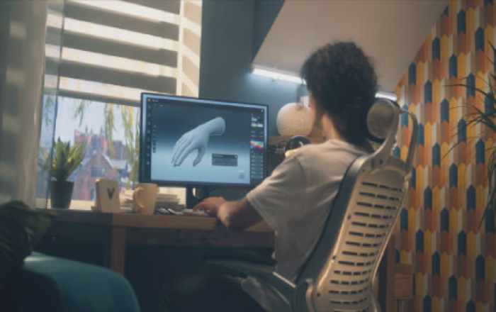
SolidWorks is a 3D design software that breathed life into the CAD industry. It uses parametric design, allowing engineers/designers to easily change the dimensions of lines/features in sketches.
Sketches can be based on the default front plane, top plane, right plane or a created plane. They can also be a combination of 2D and 3D shapes. When the Sketch is completed, it is called a model and the features become dimensions that can be changed and the results instantly show in the graphics area.
Summary:
When multiple model versions are required, an assembly file can contain the various configurations of the parts. Each configuration can reference its own component configuration, and the assembly can choose which one to display in a drawing view. Configurations can also control properties that are shown in annotations and Bill of Materials. This includes custom properties like finish, vendor and SKU. They can also control suppression states and fixed/floating positions of the mates they reference.

Vivan Henderson, a professional photographer born in Texas. Photography is his passion. He was fond of nature in his childhood. So he took his passion as a profession. He is basically nature photographer but also take other type of photo. He completed graduation in computer science from Texas Tech University. He lives in Houston with his wife and two children’s.